機構制御系のモデリング(その2) 〜回転1関節機構系を設計する〜:1Dモデリングの勘所(37)(2/4 ページ)
» 2024年11月11日 09時00分 公開
[大富浩一/日本機械学会 設計研究会,MONOist]
運動方程式で、インダクタンスと負荷トルクを無視して電圧Eを求めると、式3となる。
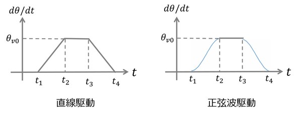
このように、電圧には角速度だけでなく、角加速度が関係し、角変位制御駆動の直線駆動では、角加速度がt1=0.1で+∞、t2=0.2で−∞となるために、図3のような結果となった。これを避けるためには、角加速度が連続的に変化するようにすればよい。そのための方法が、図4に示す角速度制御駆動で、この場合も直線駆動と正弦波駆動が考えられる。このとき、駆動時間は一定であるため、Δt=t4−t1となる。また、図4においてt1=0.1、t2=0.13、t3=0.17、t4=0.2とする。
図4の直線駆動の場合をModelicaでテキスト表現すると下記となる(リスト3 ※変更部分のみ記す)。
model rigidlinearV
―――省略―――
parameter Real t1=0.1;
parameter Real t2=0.13;
parameter Real t3=0.17;
parameter Real t4=0.2;
equation
thetav=der(theta);
thetaa=der(thetav);
E=V+R*i+L*der(i);
i=T/Kt;
V=Ke*der(theta);
T=J*thetaa+Tloss;
J=M*r^2;
thetav0=1.43*theta0/(t4-t1);
thetav = if (time<t1) then 0
elseif (time>=t1 and time<t2) then (thetav0/(t2-t1))*(time-t1)
elseif (time>=t2 and time<t3) then thetav0
elseif (time>=t3 and time<t4) then thetav0-(thetav0/(t4-t3))*(time-t3)
elseif (time>=t4) then 0
else 0;
end rigidlinearV;
リスト3 Modelicaでテキスト表現(直線駆動の場合)
同様に、図4の正弦波駆動の場合は以下となる(リスト4)。
model rigidcosV
―――省略―――
parameter Real t1=0.1;
parameter Real t2=0.13;
parameter Real t3=0.17;
parameter Real t4=0.2;
equation
thetav=der(theta);
thetaa=der(thetav);
E=V+R*i+L*der(i);
i=T/Kt;
V=Ke*der(theta);
T=J*thetaa+Tloss;
J=M*r^2;
thetav0=1.43*theta0/(t4-t1);
thetav = if (time<t1) then 0
elseif (time>=t1 and time<t2) then 0.5*thetav0*(1-cos((pi/(t2-t1))*time-(pi/(t2-t1))*t1))
elseif (time>=t2 and time<t3) then thetav0
elseif (time>=t3 and time<t4) then 0.5*thetav0*(1+cos((pi/(t4-t3))*time-(pi/(t4-t3))*t3))
elseif (time>=t4) then 0
else 0;
end rigidcosV;
リスト4 Modelicaでテキスト表現(正弦波駆動の場合)
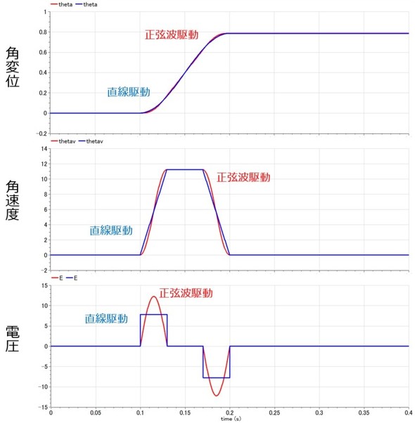
上記を解析した結果を、直線駆動と正弦波駆動で示す(図5)。このように、直線駆動、正弦波駆動で波形は異なるものの、大きさは同程度となっている。以上から、モーターのことを考えると角速度制御駆動の正弦波駆動がよいと考えられる。
Copyright © ITmedia, Inc. All Rights Reserved.
Special ContentsPR
特別協賛PR
スポンサーからのお知らせPR
Special ContentsPR
Pickup ContentsPR
メカ設計の記事ランキング
- 義手とロボットの手を共通化するPSYONICのバイオニックハンド「Ability Hand」
- 約3.5kgの力で打ち抜ける手動式卓上パンチプレス
- 高精度3Dスキャナー3機種を発売、自動検査や医療分野を支援
- 同じ機械なのに1号機はOK、2号機はNG 設計者を悩ませる“再現しない不具合”
- 新型コロナで深刻なマスク不足を3Dプリンタで解消、イグアスが3Dマスクを開発
- 【レベル4】図面の穴寸法の表記を攻略せよ!
- 令和版の健康サンダル? 否、感覚を増幅する「Nike Mind」が気になる件
- 幾何公差の基準「データム」を理解しよう
- 3σと不良品発生の確率を予測する「標準正規分布表」
- 強度設計の出発点 “計算”より先に考えるべきこととは?
Special SitePR
あなたにおすすめの記事PR
 式3
式3


