機構制御系のモデリング(その3) 〜回転2関節機構の運動学・動力学を考える〜:1Dモデリングの勘所(38)(4/5 ページ)
動力学(逆問題)
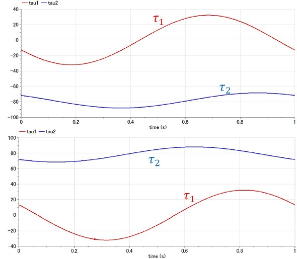
運動学の逆問題1(図5(a))、逆問題2(図5(b))と同じ条件で、回転2関節機構の動力学の逆問題を考える。まず、逆問題1をModelicaで表記すると以下となる(リスト5)。
model dynamicsReverse1
import Modelica.Constants.pi;
import Modelica.Constants.g_n;
Real theta1 (start=pi/4);
Real theta2 (start=-pi/2);
Real theta1v;
Real theta1a;
Real theta2v;
Real theta2a;
Real theta;
Real tau1;
Real tau2;
Real h1;
Real h2;
Real g1;
Real g2;
Real x;
Real y;
Real Lg;
Real M11;
Real M12;
Real M21;
Real M22;
Real In;
parameter Real L = 2;
parameter Real m = 1;
parameter Real r = 3;
parameter Real omg = 2*pi;
equation
theta1v = der(theta1);
theta1a = der(theta1v);
theta2v = der(theta2);
theta2a = der(theta2v);
Lg = L/2;
In = m*L^2/12;
M11*theta1a + M12*theta2a + h1 + g1 = tau1;
M21*theta1a + M22*theta2a + h2 + g2 = tau2;
M11 = m*Lg^2 + m*L^2 + m*Lg^2 + In + In + 2*m*L*Lg*cos(theta2);
M12 = m*Lg^2 + In + m*L*Lg*cos(theta2);
M21 = m*Lg^2 + In + m*L*Lg*cos(theta2);
M22 = m*Lg^2 + In;
h1 = -m*L*Lg*(2*theta1v + theta2v)*theta2v*sin(theta2);
h2 = m*L*Lg*theta1v^2*sin(theta2);
g1 = -m*g_n*Lg*sin(theta1)-m*g_n*L*sin(theta1)-m*g_n*Lg*sin(theta1+theta2);
g2 = -m*g_n*Lg*sin(theta1+theta2);
x = L*cos(theta1) + L*cos(theta1 + theta2);
y = L*sin(theta1) + L*sin(theta1 + theta2);
x = r*cos(theta);
y = r*sin(theta);
theta = omg*time;
end dynamicsReverse1;
リスト5について、初期条件を考慮して解くと、図10に示す2つの解が得られる。ここでは、各関節の必要トルクの挙動を示す。各関節の動きは、運動学の逆解析の結果(図6)と同じである。
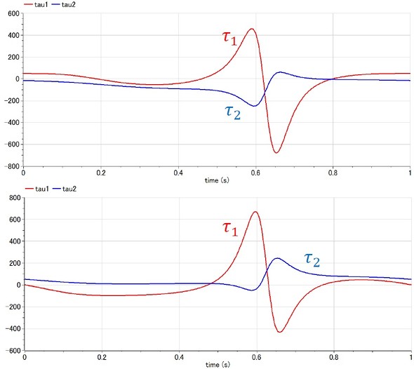
次に、逆問題2をModelicaで表記すると以下となる(リスト6)。
model dynamicsReverse2
import Modelica.Constants.pi;
import Modelica.Constants.g_n;
Real theta1 (start=pi/4);
Real theta2 (start=-pi/4);
Real theta1v;
Real theta1a;
Real theta2v;
Real theta2a;
Real theta;
Real tau1;
Real tau2;
Real h1;
Real h2;
Real g1;
Real g2;
Real x;
Real y;
Real Lg;
Real M11;
Real M12;
Real M21;
Real M22;
Real In;
Real X;
Real Y;
parameter Real L = 2;
parameter Real m = 1;
parameter Real r = 2;
parameter Real omg = 2*pi;
parameter Real x0=1;
parameter Real y0=1;
equation
theta1v = der(theta1);
theta1a = der(theta1v);
theta2v = der(theta2);
theta2a = der(theta2v);
Lg = L/2;
In = m*L^2/12;
M11*theta1a + M12*theta2a + h1 + g1 = tau1;
M21*theta1a + M22*theta2a + h2 + g2 = tau2;
M11 = m*Lg^2 + m*L^2 + m*Lg^2 + In + In + 2*m*L*Lg*cos(theta2);
M12 = m*Lg^2 + In + m*L*Lg*cos(theta2);
M21 = m*Lg^2 + In + m*L*Lg*cos(theta2);
M22 = m*Lg^2 + In;
h1 = -m*L*Lg*(2*theta1v + theta2v)*theta2v*sin(theta2);
h2 = m*L*Lg*theta1v^2*sin(theta2);
g1 = -m*g_n*Lg*sin(theta1)-m*g_n*L*sin(theta1)-m*g_n*Lg*sin(theta1+theta2);
g2 = -m*g_n*Lg*sin(theta1+theta2);
x = L*cos(theta1) + L*cos(theta1 + theta2);
y = L*sin(theta1) + L*sin(theta1 + theta2);
X=x-x0;
Y=y-y0;
X = r*cos(theta);
Y = r*sin(theta);
theta = omg*time;
end dynamicsReverse2;
リスト6について、初期条件を考慮して解くと、図11に示す2つの解が得られる。各関節の必要トルクの挙動を示す。事例1(図10)と比べると、関節の動きが複雑で、その分、大きなトルクを必要としていることが分かる。なお、各関節の動きは、運動学の逆解析の結果(図7)と同じである。
Copyright © ITmedia, Inc. All Rights Reserved.
メカ設計の記事ランキング
- 義手とロボットの手を共通化するPSYONICのバイオニックハンド「Ability Hand」
- 約3.5kgの力で打ち抜ける手動式卓上パンチプレス
- 高精度3Dスキャナー3機種を発売、自動検査や医療分野を支援
- 同じ機械なのに1号機はOK、2号機はNG 設計者を悩ませる“再現しない不具合”
- 新型コロナで深刻なマスク不足を3Dプリンタで解消、イグアスが3Dマスクを開発
- 【レベル4】図面の穴寸法の表記を攻略せよ!
- 幾何公差の基準「データム」を理解しよう
- 令和版の健康サンダル? 否、感覚を増幅する「Nike Mind」が気になる件
- 3σと不良品発生の確率を予測する「標準正規分布表」
- 強度設計の出発点 “計算”より先に考えるべきこととは?


